- Flex PCB Blog
- PCB Assembly Blog
- FPC Research Blog
- Preparation of FPC based on ultrasonic spraying method_4_Experimental Results
- Preparation of FPC based on ultrasonic spraying method_3_Experimental Procedure
- Preparation of FPC based on ultrasonic spraying method_2_Experimental Platform and Principle
- Preparation of FPC based on ultrasonic spraying method_1_abstract
- Research on Layout Design Method of Ultra-thin FPC_4_Analysis of Layout Design Methods
- Research on Layout Design Method of Ultra-thin FPC_3_Analysis of Layout Design Methods
- Research on Layout Design Method of Ultra-thin FPC_2_Analysis of Layout Design Methods
- Research on Layout Design Method of Ultra-thin FPC_1_introduction
- Research progress on polyimide FPC_2_the field of FPC
- Research progress on polyimide FPC_1_Introduction
- Analysis of Vibration Characteristics of FPCBs _4_Summary
- Analysis of Vibration Characteristics of FPCBs _3_Finite Element Analysis
- Analysis of Vibration Characteristics of FPCBs _2_Theory of Vibration Analysis
- Analysis of Vibration Characteristics of FPCBs Under Random Vibration_1_Introduction
- Design Methods for FPCBs_5_Practical Application
- Design Methods for FPCBs_4_Electrical Circuit Design and Examples
- Design Methods for FPCBs_3_Structure Design Method and Examples
- Design Methods for FPCBs_2_Component Selection Methodology and Examples.
- Research on Design Methods for FPCBs
- Application of MPW technique for FPCBs _4_Summary
- Application of MPW technique for FPCBs_3_Experimental results
- Application of MPW technique for FPCBs_2_Experimental setup
- Application of MPW technique for FPCBs_1_Principle of MPW
- Application of FPCB in PC motherboards_4_ Results and discussion
- Application of FPCB in PC motherboards_3_ Numerical analysis
- Application of FPCB in PC_2_ Experimentation
- Application of FPCB in PC motherboards
- A Bus Planning Algorithm for FPC Design _4_Experimental result
- A Bus Planning Algorithm for FPC Design _3_Proposed Algorithm
- A Bus Planning Algorithm for FPC Design _2_Preliminaries
- A Bus Planning Algorithm for FPC Design _1_Introduction
Application of flexible printed circuit board (FPCB) in personal computer motherboards
Focusing on mechanical performance_4_ Results and discussion
4. Results and discussion
4.1. Experimental measurements versus numerical predictions
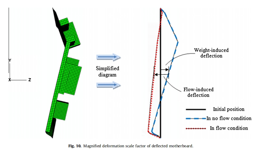
For the motherboard in the flow condition, two types of forces are involved, namely, weight-induced force and flow-induced force. Weight-induced force is due to the own weight of the motherboard whereas flow-induced force is due to the air flow influence. These forces significantly affect the deflections of the motherboard, as clearly seen in Fig. 10. In the present study, deflection is defined as the displacement in the z-direction.
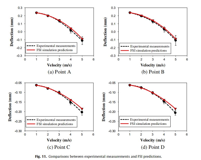
The FPCB deflections from the FSI numerical predictions are compared with the experimental measurements. The comparisons are performed for various velocities at Points A, B, C, and D, as shown in Fig. 11. At higher velocity, the simulation is observed to tend to predict a lower magnitude of flow-induced deflections (which move to the negative z-direction), thereby resulting in a more positive value of deflections. This phenomenon may be attributable to the existence of slight turbulence in the air flow,which can be initiated under the actual running condition of the experiment. However, the comparisons show good agreement be- tween numerical predictions and the experimental measurements in terms of changing trends, as well as magnitudes. The average magnitude discrepancy was found to be approximately 9%. Based on the 90% confidence interval consideration, the repetition error (error bars in Fig. 11) during the measurements was found to be around 10%. Therefore, this simulation technique is applied in the present study because of its accurate prediction, cost and time savings, and capability to provide full field distribution contours.
4.2. Effect of flow velocity
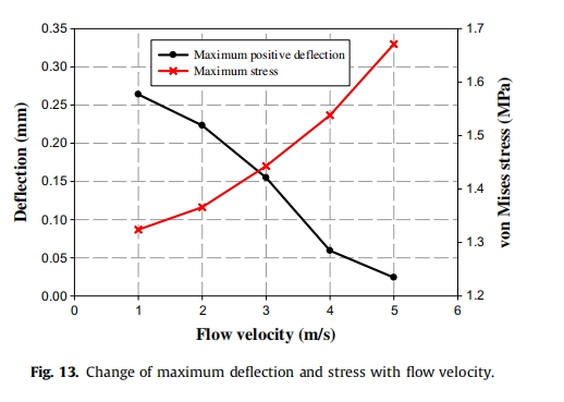
The effect of flow velocity is investigated in one configuration (Fasten 1 and Layout 1), which resembles the experimental test vehicle. The deflection and stress contours for flow velocities of 1, 3, and 5 m/s are shown in Fig. 12. Based on the results, most of the stresses were shown to accumulate at the fixed regions, with the bottom fix withstanding the significant stress in the entire motherboard. As shown in Fig. 13, this maximum induced stress (at the bottom fix) increases with the flow velocity, achieving a maximum of 1.67 MPa at flow velocity of 5 m/s because, at higher velocity, the air flow becomes more vigorous and subsequently has a greater effect on the motherboard.
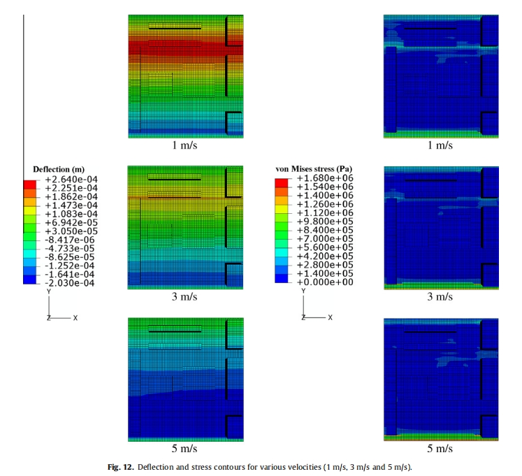
In addition, as flow velocity increases, the motherboard is noticed to tend to deflect toward the negative z-direction, which also indicates that the flow forces are acting in this direction. However, the positive z-deflection is found in the deflection contours because these contours are the resultant of both flow- and weight-induced forces. At the highest flow velocity, although the flow-induced deflection is the highest, the result ant deflection is noted to decrease because the weight-induced deflection (in the positive z-direction) is canceled by the flow-induced deflection (in the negative z-direction). At this juncture, the effect of air flow, which is often ignored in rigid motherboard systems, is important for the deflection and stress levels when dealing with an FPCB motherboard.
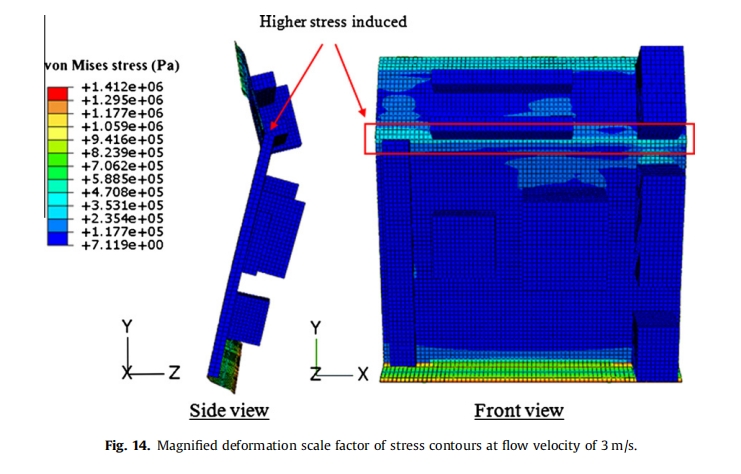
Furthermore, the motherboard deflection profile is seen to be shaped according to its attached components, as shown in the magnified deformation scale factors of the contours in Fig. 14. The motherboard deflects toward the positive z-direction at its upper portion and toward the negative z-direction at its lower portion. Remarkably, the motherboard deflection profile is predominantly affected by the memory slot component because of the orientation of the memory slot across the motherboard. This deflection behavior presents an explanation on the phenomenon, in which comparably higher stress is induced at the region, as shown in Fig. 14. In practice, any attempt to minimize induced deflection and stress would be desirable for FPCB motherboard systems.
4.3. Effect of different fastening options
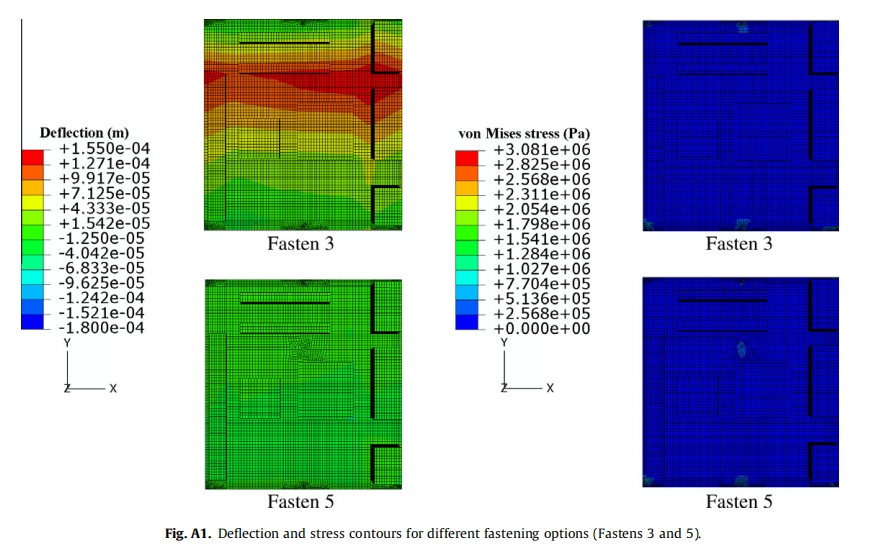
Few fastening options (as shown in Fig. 8) are generated and investigated. The effect of these fastenings is studied on one configuration (Layout 1) at a flow velocity of 3 m/s. The results for Fastens 1, 2, and 4 are shown in Fig. 15 to illustrate the different configurations, namely,edge clamping, screw fastening, and outcome of middle screwing. The results of Fastens 3 and 5 are provided in Fig. A1.
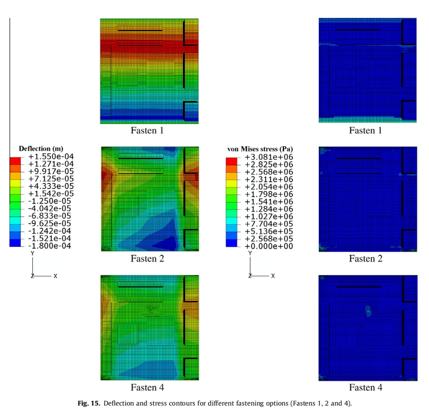
As observed in Fasten 1, the deflection of the motherboard is almost uniform along the horizontal direction because the mother- board is edge clamped at the top and bottom sides. By contrast, the uniformity of deflection in the horizontal direction no longer exists when screw fasteners are used (Fastens 2, 3, 4, and 5) be- cause the deformation patterns produced are now largely dependent on the location of the screws. In general, a greater number of fastening screws can reduce the magnitude of the maximum induced deflection and stress in the motherboard.
In Fig. 16, the maximum stress increases substantially as the option is changed from Fasten 1 (1.44 MPa) to Fasten 2 (3.08 MPa), although the maximum deflections are nearly identical because the sustaining stress in Fasten 2 is limited to only a few fastening spots at the corners. However, in terms of maximum deflection and stress,this phenomenon can be improved by adding two more fastening screws, as shown in Fasten 3. For Fastens 4 and 5, both maximum induced deflection and stress can be significantly reduced by introducing an additional fastening screw at the middle of the motherboard.
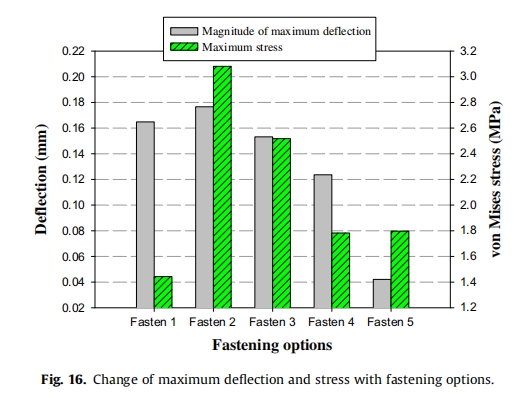
Compared with Fasten 4, Fasten 5 provides a slightly higher maximum stress, but its maximum deflection is reduced to a great extent. Therefore, Fasten 5 is the most suitable option for application to FPCB motherboards. The secondary choice would be Fasten 4. In addition, the designers can also consider incorporating some stiffeners in the vicinity of the fastening screws based on the finding that majority of the stresses are built up in this area. If possible, the components should as well be placed at some distance from the fastening screws to avoid unnecessary strain in the component joints.
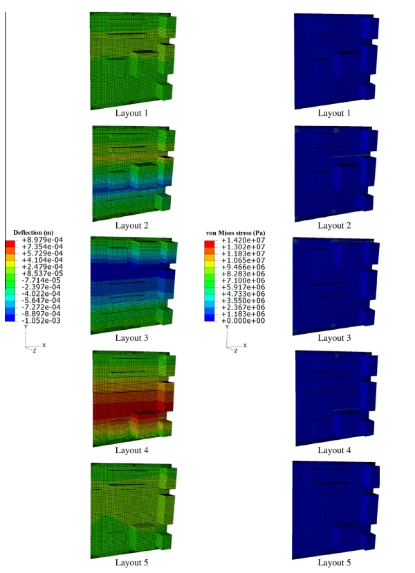
4.4. Effect of different component layouts
Different component layouts (as shown in Fig. 9) are also investigated. The present study is conducted on one configuration (Fasten 3) at a flow velocity of 3 m/s. The results are shown in Fig. 17, and the contours are provided in Fig. A2.
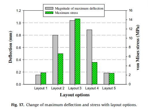
Accordingly, the maximum deflection and stress rapidly increase when the memory slots are configured in the horizontal orientation, as seen in Layout 2, because memory slots that are configured with a vertical orientation can provide some strengthening effect toward the entire motherboard structure. On the other hand, the worse case occurs forLayout3,whichhastwobiggercomponents(heatsinkand CPU fan) located at the upper motherboard, because it gives the largest deflection (1.04 mm) and the highest stress (14.2 MPa). Comparing Layouts 2 and 4, Layout 4, where the heat sink and CPU fan are located at the lower part of the motherboard, is seen to provide a slightly higher maximum deflection, but its associated maximum stress is significantly reduced. Given this finding, good sense would prevail to consider Layout 1 with the heat sink and CPU fan located at the lower part of motherboard; hence, Layout 5 is considered for investigation. As expected, a similar trend is also obtained when comparing Layout 1 with Layout 5, but the stress reduction has become less prominent.
Therefore, during the design of the motherboard, configuring the memory slots in a vertical orientation is advisable to mitigate the stiffness of the motherboard. More importantly, for enhanced reliability, the heat sink and CPU fan should not be located at the upper part of the motherboard to avoid unnecessary massive induced deflection and stress. Among the options investigated, in the opinion of the authors, Layouts 1 and 5 are both acceptable. Ultimately, the effect of component layouts is obviously more prominent in the induced deflection and stress of the FPCB motherboard compared with the effects of fastening options and flow velocity.
4.5. Mechanical feasibility of FPCB as motherboard
Among all the cases considered, the maximum deflection and stress are found to be in the ranges of 0.02–1.04 mm and 1.32– 14.2 MPa, respectively. Under the worse condition, the maximum deflection can reach up to 1.04 mm, whereas the maximum stress can reach up to 14.2 MPa. Such a deflection should be carefully considered to guarantee that the FPCB motherboard would not be in contact with other surrounding objects, especially in miniaturized PCs.
Compared with the yield strength of FPCB (80MPa), as discussed in Section 2.1, most of the stress values discovered in the case studies are still acceptable. However, this issue should not be disregarded to ensure that motherboard reliability is secured in the long run because an FPCB motherboard is significantly more sensitive to induced deflection and stress. The worse stress condition (14.2MPa) should be carefully addressed.
In terms of the mechanical aspects, the authors believe that the potential of FPCB as a motherboard is feasible provided that some concerns on the induced deflection and stress are addressed. How- ever, more detailed analyses on the other influence factors, including mechanical and electronic circuit aspects, should be conducted before the FPCB motherboard can finally be commercially used.
5. Conclusion
The current paper has outlined the study on the feasibility of FPCB as a substrate for PC computer motherboards. The effects of increasing inlet velocity, fastening options, and different component layouts based on the FSI analysis are studied. The current study was numerically performed using FLUENT and ABAQUS codes, coupled online by MpCCI. The predictions were validated with the experimental results, and both were shown to be in good agreement. As the flow velocity increases, the deflection and stress in the motherboard also increase.
In general, a greater number of fastening screws provide lesser deflection and stress conditions. An additional fastening screw at the middle of the motherboard remarkably improves the deflection and stress conditions. The results show that Fasten 5 is the best in terms of deflection and stress.
The layout of components significantly affects the deflection and stresses on the FPCB motherboard. Vertically oriented memory slots can significantly strengthen the motherboard. The deflection and stress conditions in the motherboard would substantially deteriorate if the two bigger components (heat sink and CPU fan)are located at the upper portion. The results show that both Layouts 1 and 5pro- vide the best component arrangement for an FPCB motherboard. Although the present study on FPCB is primarily focused on the motherboard, the findings could also contribute valuable information for other FPCB applications. The present study can be further extended into electrical circuit and electronic signal considerations, so that this novel approach can also be electronically feasible.